
An end bearing plate is a flat steel plate that transfers concentrated loads from a steel column directly onto a concrete or masonry foundation, preventing localized crushing and structural failure. Known formally in structural engineering as a column base plate, this component sits at the critical interface between steel and concrete. AISC 360-22 and ACI 318-19 govern its design, making compliance with these standards non-negotiable for any load-bearing application. Getting the plate right protects every structural element above it.
What is an end bearing plate and why does it matter?
An end bearing plate distributes a column's point load across a larger surface area, reducing the bearing stress on the concrete below to a safe level. Without it, a steel column would punch into the foundation like a nail through drywall. AISC specifications require that bearing plates prevent local yielding or crushing of the supporting wall or foundation. That single requirement drives every design decision that follows.
Column base plate design balances three interdependent elements: the plate itself, the concrete bearing surface, and the anchor bolts under axial compression and shear. Each element affects the others. A plate sized only for axial load may fail under combined shear and moment. Engineers who treat these as separate checks rather than a unified system create hidden vulnerabilities.
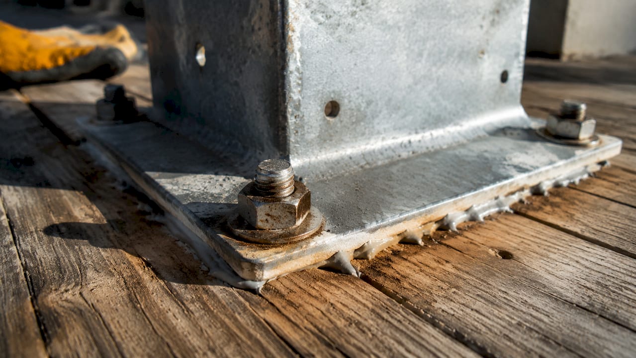
The stakes are high in practice. A bearing plate that is too small concentrates stress beyond the concrete's capacity. One that is too thick adds unnecessary cost and creates welding and leveling problems in the field. The goal is a plate that is exactly right for the load condition, the concrete strength, and the construction sequence.
What are the main types and materials used?
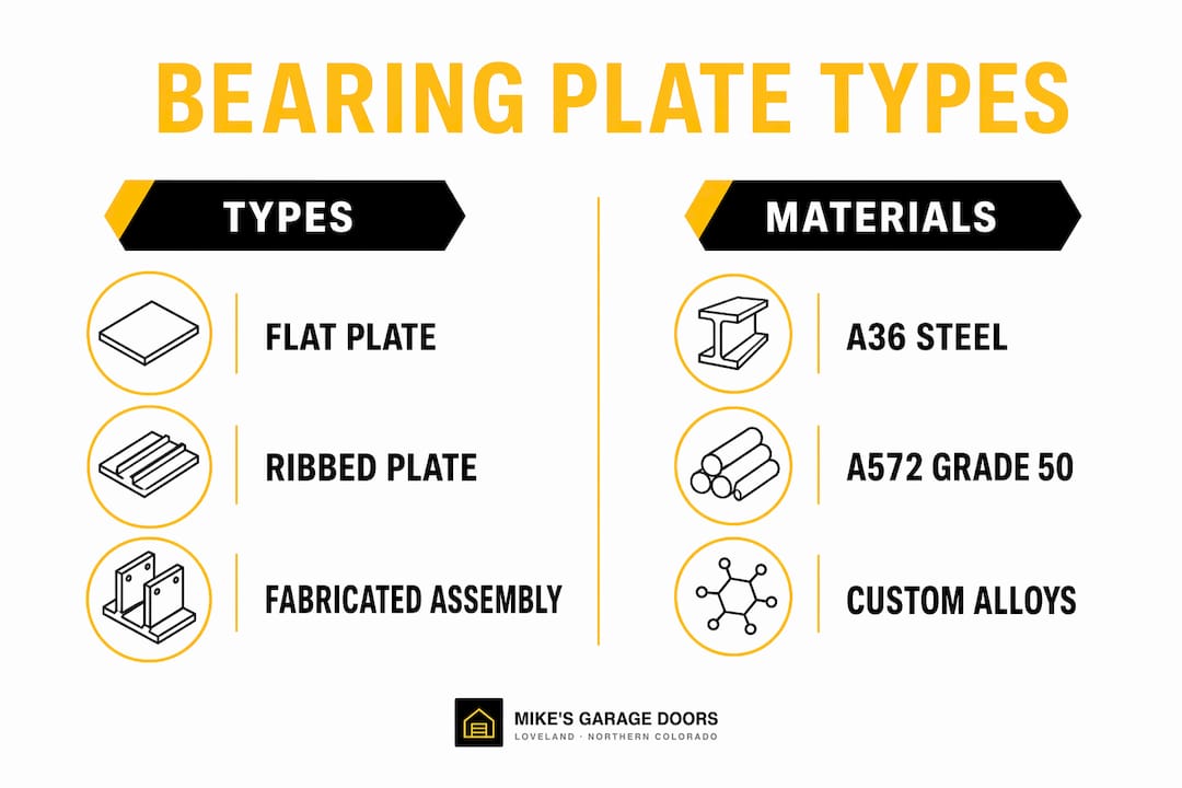
Structural bearing plates fall into three practical categories: flat plates, ribbed plates, and custom fabricated assemblies. Each serves a different load range and application.
Flat plates are the most common. They work well for axial loads without significant moment and are straightforward to fabricate and install. Ribbed plates add stiffening ribs to the underside, increasing bending resistance without adding full plate thickness. Custom fabricated assemblies combine base plates with welded stiffeners, shear lugs, and pre-drilled anchor bolt patterns for heavy industrial or seismic applications.
Material selection follows load requirements closely. The two most common structural steel grades are:
- ASTM A36: Yield strength of 36 ksi. Used for lighter loads and standard commercial construction. Cost-effective and widely available.
- ASTM A572 Grade 50: Yield strength of 50 ksi. Preferred for heavier loads where a thinner plate is needed to reduce weight and material cost.
| Type | Material | Typical Thickness | Common Applications |
|---|---|---|---|
| Flat plate | A36 or A572 Gr 50 | 3/4 in. to 2 in. | Light to medium columns, standard commercial |
| Ribbed plate | A572 Gr 50 | 1/2 in. to 1-1/2 in. | Medium loads, where weight reduction matters |
| Custom fabricated | A572 Gr 50 or higher | 1 in. to 3+ in. | Heavy industrial, seismic zones, moment connections |
A36 costs less per pound but requires more material to achieve the same strength. A572 Grade 50 reduces plate area and thickness, which often offsets the higher material cost on larger projects. For most structural applications today, A572 Grade 50 is the default choice.
How do engineers calculate plate size and thickness?
Bearing plate design starts with the required plate area. The formula divides the factored column load by the allowable concrete bearing stress, which depends on both concrete compressive strength and the confinement factor. Upgrading concrete compressive strength from 21 MPa to 28–32 MPa can reduce the required plate surface area by 30–40%. That reduction directly lowers material and fabrication costs on large projects.
The confinement factor accounts for the ratio of the total concrete area (A2) to the plate bearing area (A1). When the concrete extends well beyond the plate footprint, the concrete can carry higher stress due to lateral confinement. Engineers calculate the square root of A2/A1, capped at 2.0 per ACI 318-19, and apply it to the base bearing stress. This is one of the most commonly misapplied factors in bearing plate design.
Plate thickness uses a cantilever bending model. The plate acts as a cantilever projecting beyond the column flanges, bending under the upward bearing pressure from the concrete. The required thickness increases with the cantilever length and the bearing pressure. The table below shows representative values:
| Factored Load (kips) | Plate Size (in.) | Concrete f'c (psi) | Required Thickness (in.) |
|---|---|---|---|
| 200 | 12 x 12 | 3,000 | 1.00 |
| 400 | 16 x 16 | 3,000 | 1.25 |
| 600 | 18 x 18 | 4,000 | 1.50 |
| 900 | 22 x 22 | 4,000 | 1.75 |
Unstiffened plates thicker than 3 inches are impractical in most field conditions. Adding stiffeners reduces the required thickness by 30–50% and improves force transfer by changing the bending model from a simple cantilever to two-way plate bending. Stiffeners are the right answer when calculations push thickness beyond 2.5 inches.
Pro Tip: Always check whether the governing load case is axial only or combined axial plus moment. A plate sized for axial load alone can be dangerously undersized when column moments are present, particularly at frame corners and moment connections.
Designing end plates to achieve Mode 2 failure, where bolt failure occurs with partial plate yielding, produces ductile and predictable behavior under seismic and high-load conditions. This is the preferred failure mode in modern seismic design because it gives visible warning before collapse.
How does shear transfer work through bearing plates?
Shear transfer is the part of bearing plate design that gets the least attention and causes the most failures. Friction at the grout-to-steel interface handles moderate horizontal loads. The friction coefficient at a grouted steel interface is 0.55, meaning the plate can resist horizontal force equal to 55% of the vertical clamping force from the anchor bolts. When horizontal loads exceed that capacity, friction alone is not enough.
When friction is insufficient, engineers add shear lugs or mechanical anchors. A shear lug is a steel plate or bar welded to the underside of the bearing plate and embedded in the concrete. It transfers shear through direct bearing rather than friction, making it far more reliable under large lateral loads or seismic demands. Anchor bolts contribute to shear resistance as well, but their primary function is tension under uplift.
Common failure modes in shear transfer include:
- Anchor bolt overload: Bolts sized only for tension fail when combined shear and tension loads exceed their interaction capacity.
- Grout deterioration: Cracked or poorly placed grout eliminates the friction mechanism entirely.
- Missing shear lugs: Plates designed without shear lugs in high-shear zones rely entirely on friction, which is unreliable over time.
- Uneven bolt tightening: Poor installation practices such as uneven anchor bolt tightening cause stress concentrations that crack the grout and misalign the plate.
Pro Tip: Specify torque values for anchor bolt tightening in the construction documents. "Snug tight" is not a torque value. Inconsistent tightening is one of the leading causes of grout cracking and plate settlement after erection.
Critical installation steps for reliable shear transfer include cleaning the concrete surface before grouting, using non-shrink grout at the correct water-to-cement ratio, and tightening anchor bolts in a cross pattern to distribute clamping force evenly. These steps take minutes. Skipping them can mean months of remediation.
How do you coordinate bearing plate installation with other systems?
Bearing plates do not exist in isolation. They sit at the intersection of structural steel, concrete foundations, anchor bolt systems, mechanical embedments, and sometimes architectural finishes. Treating bearing plates as isolated components rather than part of a coordinated system is the leading cause of interface failures in precast and steel construction.
3D BIM coordination before fabrication is the single most effective way to avoid field problems. Fabrication should begin only after BIM coordination confirms no conflicts with embedded components. Anchor bolt patterns that clash with rebar mats, conduit runs, or drain sleeves are common in dense foundation conditions. Finding these conflicts in the model costs nothing. Finding them in the field costs days.
Practical coordination checklist for bearing plate installation:
- Verify anchor bolt projection heights against the plate thickness and leveling nut requirements before concrete is placed.
- Confirm grout pocket dimensions allow full grout flow under the plate without air pockets.
- Check that plate elevation matches the structural drawings after accounting for grout bed thickness, typically 1 to 2 inches.
- Coordinate with mechanical and electrical trades to avoid embedments within the plate footprint.
- Confirm weld access for any field welding of shear lugs or stiffeners after erection.
Plates thinner than 3/4 to 1 inch often warp during welding, making leveling difficult and requiring shimming that was not planned for. Specifying a minimum practical thickness of 3/4 inch prevents this problem. Leveling nuts on the anchor bolts allow fine adjustment of plate elevation before grouting, which is far easier than shimming after the fact.
Temporary stability during erection also requires planning. Until grout cures, the plate and column rely entirely on the anchor bolts for stability. Wind loads, construction equipment vibration, and erection forces all act on the ungrouted connection. Bracing requirements during this phase belong in the erection plan, not as an afterthought.
Key Takeaways
End bearing plate performance depends on accurate load calculations, correct material selection, and disciplined installation. Skipping any one of these three steps creates risk that no amount of overdesign in the others can fully offset.
| Point | Details |
|---|---|
| Design to combined loads | Size the plate for axial load plus moment and shear, not axial load alone. |
| Use concrete strength to reduce plate size | Upgrading to 28–32 MPa concrete can cut required plate area by 30–40%. |
| Add stiffeners before exceeding 2.5 inches | Stiffeners reduce thickness by 30–50% and improve two-way force transfer. |
| Specify torque for anchor bolts | Uneven tightening causes grout cracking and is a leading installation failure cause. |
| Coordinate in 3D before fabrication | BIM clash detection before fabrication eliminates costly field corrections. |
What I've learned from watching bearing plates fail in the field
The uncomfortable truth about bearing plate failures is that most stem from installation errors, not design flaws. I've seen beautifully engineered plates installed on contaminated concrete surfaces, grouted with the wrong mix, and bolted with a standard wrench instead of a torque wrench. The plate was perfect. The installation was not.
The second pattern I keep seeing is late-stage coordination. Engineers finalize the plate design, fabricators cut the steel, and then someone discovers the anchor bolts land directly on a rebar cage. Construction interface clashes cause delays that are entirely preventable with early 3D coordination. The technology exists. The discipline to use it early enough is what's missing.
My recommendation to builders and engineers is simple. Treat the bearing plate connection as a system, not a component. That means the plate, the grout, the anchor bolts, the concrete, and the erection sequence all get reviewed together before a single piece of steel is cut. The design codes give you the math. The field gives you the consequences.
— Eddie
Structural installation support from Mikes garage doors Loveland
Mikes garage doors Loveland understands that structural components and precise installation go hand in hand. Whether you're coordinating a garage door system with structural framing or need expert help with component-level repairs in Northern Colorado, the team brings the same attention to detail that bearing plate work demands.

With same-day repair services covering springs, openers, commercial doors, and custom installations, Mikes garage doors Loveland delivers upfront phone estimates with no surprise costs. Veterans receive a 10% discount. Call today and get a straight answer from a team that knows the work.
FAQ
What is an end bearing plate in structural engineering?
An end bearing plate is a flat steel plate placed between a column base and a concrete foundation to distribute concentrated loads over a larger area. It prevents localized crushing of the concrete and is designed per AISC 360-22 and ACI 318-19.
What steel grade is best for bearing plates?
ASTM A572 Grade 50 is the preferred choice for most structural bearing plates because its higher yield strength (50 ksi) allows thinner, lighter plates compared to A36. A36 remains cost-effective for lighter load applications.
When do bearing plates need stiffeners?
Stiffeners are required when the calculated plate thickness exceeds approximately 2.5 to 3 inches. Adding stiffeners reduces the required thickness by 30–50% and converts the bending model from a simple cantilever to two-way plate bending.
How is shear transferred through a bearing plate?
Shear transfers through friction at the grout-to-steel interface, with a friction coefficient of 0.55. When horizontal loads exceed the friction capacity, shear lugs or mechanical anchors embedded in the concrete carry the remaining shear through direct bearing.
What causes most bearing plate connection failures?
Poor installation practices cause most failures, specifically inadequate surface preparation, incorrect grout mix, and uneven anchor bolt tightening. Design errors are far less common than execution errors in the field.